Substations And Overhead Lines
The breaker switches load current and interrupts overload and short-circuit current in three-phase, 50 Hz systems. Applications include utility substations, power plants and industrial or mining networks.


Scan To Chat On WhatsApp
GreenPower
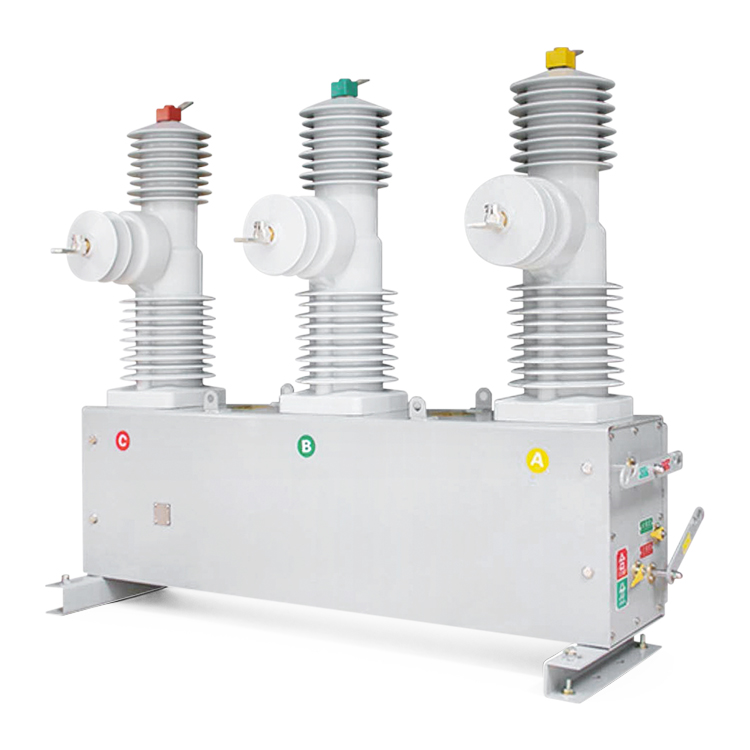
ZW7-40.5kV is an outdoor vacuum circuit breaker for substations and overhead lines in 33-40.5 kV power systems. The series offers rated currents from 630 A to 2500 A and short-circuit breaking ratings of 20 kA, 25 kA and 31.5 kA. Conventional interrupter assemblies and embedded-pole designs are available, with porcelain or silicone rubber external insulation according to the selected variant.
The breaker switches load current and interrupts overload and short-circuit current in three-phase, 50 Hz systems. Applications include utility substations, power plants and industrial or mining networks.
An FTU controller, voltage transformer and metering equipment can be combined with the breaker for protection, automatic reclosing, remote control and energy metering.
The series is rated for 95 kV power-frequency withstand for one minute and 185 kV lightning impulse withstand.
Up to three current transformers can be fitted, with up to four cores per CT. Ratios, accuracy classes and burdens are selected for the protection and metering circuits.
The mechanism enclosure uses drainage grooves and foam door seals. A temperature controller and heater help limit condensation inside the enclosure.
| Parameter | Data |
|---|---|
| Rated Voltage | 40.5 kV |
| Rated Current | 630 A / 1250 A / 1600 A / 2000 A / 2500 A |
| Rated Frequency | 50 Hz |
| Rated Short-Circuit Breaking Current | 20 kA / 25 kA / 31.5 kA |
| Rated Short-Time Withstand Current | 20 kA / 25 kA / 31.5 kA, 4 s |
| Rated Peak Withstand Current | 50 kA / 63 kA / 80 kA |
| Rated Short-Circuit Making Current (Peak) | 50 kA / 63 kA / 80 kA |
| 1-Minute Power-Frequency Withstand Voltage | 95 kV |
| Lightning Impulse Withstand Voltage (Peak) | 185 kV |
| Opening, Closing And Auxiliary Supply | 110 V AC/DC or 220 V AC/DC |
| Rated Operating Sequence | O - 0.3 s - CO - 15 s - CO |
| Opening Time | 20-50 ms |
| Closing Time | 30-80 ms |
| Rated Cable Charging Breaking Current | 50 A |
| Endurance Classes Listed | E2 / C2 / M2 |
| Mechanical Life | 10,000 operations |
| Interruptions At Rated Short-Circuit Breaking Current | 20 operations |
These are series ratings. Confirm the available current, short-circuit rating and structure combination for the selected model. O denotes opening; CO denotes closing followed by opening.
| Model | Interrupter Construction | External Insulation |
|---|---|---|
| ZW7A-40.5 | Conventional interrupter assembly | Porcelain or silicone rubber |
| ZW7B-40.5 | Conventional interrupter assembly | Porcelain or silicone rubber |
| ZW7C-40.5 | Embedded pole | Porcelain or silicone rubber |
| ZW7D-40.5 | Embedded pole | Silicone rubber |
| ZW7E-40.5 | Embedded pole | Silicone rubber |
The ordering table lists 1250 A configurations for ZW7D and ZW7E. CT location, rated current and altitude capability depend on the selected structure. Use the confirmed model and assembly drawing when ordering.
The standard arrangement uses a spring operating mechanism; the manual identifies the CT19BW mechanism. Opening, closing and motor energy-storage supplies can be specified at 110 V or 220 V, AC or DC.
The model designation and ordering schedule also include an M-type permanent-magnet mechanism. Specify this option with its operating power supply and control interface.
| Configuration | Selection Details |
|---|---|
| Current Transformers | Up to three CTs, with up to four cores per CT. The manual lists primary ratings from 25 A to 2000 A with a 5 A secondary; special ratios and 1 A secondaries can be discussed. |
| Metering And Protection Cores | Typical combinations include 0.2S and 0.5 metering cores with 5P20 or 10P10 protection cores. Specify each core's ratio, accuracy class and burden. |
| Voltage Transformers | External PTs are optional. The ordering schedule includes 35/0.1 kV, 35/0.22 kV and 35/0.1/0.22 kV ratios for the associated 35 kV system; confirm the ratio for the actual installation. |
| FTU Protection And Reclosing | With a suitable FTU arrangement, the intelligent assembly supports fault detection, protection, automatic reclosing and remote monitoring and control. Select functions with the required protection scheme. |
| Metering And Payment Control | The JLFK arrangement adds metering and payment-control functions using the specified CTs, PTs, controller and meter box. These are optional assembly components. |
| Enclosures And Supports | The ordering schedule includes coated steel and stainless-steel enclosure options, mounting supports and surface finishes. Confirm materials, support height and installation interfaces. |
The optional intelligent assembly uses sealed outdoor control cables and plug connections. Confirm the complete supply scope, controller functions and wiring diagrams with the order.
-30°C to +40°C; the 24-hour average must not exceed +35°C.
Not exceeding 1000 m. Higher-altitude equipment requires a specified configuration.
Relative humidity: daily average up to 95%, monthly average up to 90%. Water-vapour pressure: daily average up to 2.2 kPa, monthly average up to 1.8 kPa.
Wind speed up to 34 m/s; ice thickness up to 20 mm.
Pollution level II under normal conditions; seismic intensity not exceeding degree 8.
Higher pollution, severe condensation, salt spray and extreme temperatures require review before ordering.
The manual describes configurations for 2000 m, 3000 m, 4000 m and 5000 m. These require changes to the selected structure and insulation clearances; the full altitude range is not shared by every variant.
Mounting arrangements and foundation dimensions differ by structure and altitude version. Confirm the complete assembly, support, terminal positions and foundation drawing before site work.
The catalog includes dimensioned drawings for the individual variants. Download it for reference and request the final drawing for the ordered configuration.
The manual references the following circuit-breaker and switchgear standards. Confirm the required editions and documentation for the project.
Send the rated current, short-circuit level, structure type and site altitude. Include the mechanism supply, CT/PT requirements, mounting arrangement and any protection, reclosing or metering functions required.