Outdoor Distribution Protection
The three-phase pillar arrangement serves outdoor distribution circuits, including locations with frequent switching and urban or rural network upgrades.


Scan To Chat On WhatsApp
GreenPower
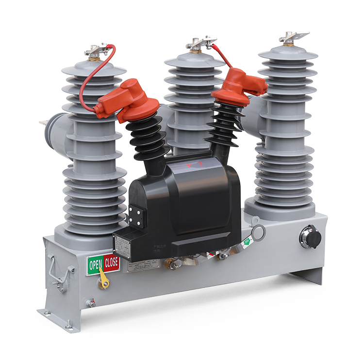
ZW32-24kV is a pole-mounted outdoor vacuum circuit breaker for three-phase, 50 Hz distribution systems. It switches load current and interrupts overload and short-circuit currents in substation, industrial, mining and rural distribution networks. Spring and permanent-magnet mechanisms are available. With a matched controller, the breaker can provide automatic reclosing and distribution automation functions.
The three-phase pillar arrangement serves outdoor distribution circuits, including locations with frequent switching and urban or rural network upgrades.
Specify the controller, protection settings, voltage sensing and communication requirements together. Reclosing and remote operation depend on the selected breaker-and-controller arrangement.
The breaker supports local manual and electrical operation. A matched controller provides remote operation for distribution automation schemes.
Choose a T-type spring mechanism or an M-type permanent-magnet mechanism. Their rated mechanical lives are 10,000 and 30,000 operations respectively.
Two-phase or three-phase current transformer arrangements can be specified. Select single or multiple ratios and the accuracy combination required by the protection and metering circuits.
| Parameter | Data |
|---|---|
| Rated Voltage | 17.5 kV / 24 kV |
| Rated Current | 630 A / 1250 A |
| Rated Frequency | 50 Hz |
| Rated Short-Circuit Breaking Current | 20 kA / 25 kA |
| Rated Short-Time Withstand Current | 20 kA / 25 kA, 4 s |
| Rated Peak Withstand Current | 50 kA / 63 kA |
| Rated Short-Circuit Making Current (Peak) | 50 kA / 63 kA |
| Mechanical Life - Spring Mechanism | 10,000 operations |
| Mechanical Life - Permanent-Magnet Mechanism | 30,000 operations |
| 1-Minute Power-Frequency Withstand Voltage (Wet) | 50 kV to ground and phase-to-phase |
| 1-Minute Power-Frequency Withstand Voltage (Dry) | 65 kV to ground and phase-to-phase; 79 kV across open contacts |
| Lightning Impulse Withstand Voltage (Peak) | 125 kV |
| Interruptions At Rated Short-Circuit Breaking Current | 30 operations |
| Rated Operating Sequence | O - 0.3 s - CO - 180 s - CO |
| Secondary Circuit 1-Minute Power-Frequency Withstand Voltage | 2000 V |
Select the current and short-circuit ratings for the required configuration. O denotes opening; CO denotes closing followed by opening.
Rated mechanical life is 10,000 operations. The manual describes an FDK-10 composite controller for the spring version, with inrush-current delay, overcurrent protection and short-circuit tripping.
Rated mechanical life is 30,000 operations. The manual includes a SAF5-CE controller arrangement for the permanent-magnet mechanism, with protection, reclosing and communication functions.
Controller models and enabled functions should be specified with the ordered breaker. Confirm the operating power supply, mechanism interface and required reclosing scheme.
The functions below are listed for the SAF5-CE controller configuration described in the manual. Confirm the required hardware, firmware and enabled protocols for the selected 24 kV installation.
| Controller Item | Functions And Data |
|---|---|
| Reclosing And Synchronism Check | Automatic reclosing (ANSI 79) and synchronism check (ANSI 25). |
| Protection Functions Listed | Phase overcurrent, overload, zero-sequence and ground-fault protection, voltage protection and frequency protection. |
| Current And Voltage Measurement Error | Not exceeding 0.5% for the listed controller. |
| Sequence Of Events Resolution | Not exceeding 2 ms. |
| Communication Interfaces | RS232 × 2, RS485 × 1, RJ45 Ethernet access. |
| Communication Protocols Listed | IEC 61850, IEC 60870-5-101/104, DNP3.0 and Modbus-RTU. |
| SAF5-CE Protection Level Listed | IP55 |
The IP55 value above belongs to the listed controller configuration. Confirm the complete breaker, controller enclosure and installation requirements during selection.
The manual lists single ratios from 50/5 A to 1250/5 A, and multiple-ratio examples including 100-200-300/5 A, 200-400-600/5 A and 600-800-1000/5 A. Accuracy options include 0.2S, 0.2, 0.5S, 0.5 and 10P in selected combinations.
Single-side or dual-side external voltage transformers can supply operating power for the breaker and controller. Specify whether voltage measurement or voltage protection is also needed, and confirm the PT ratio and secondary connections.
The breaker can be installed on a single pole or a double pole using a dedicated steel frame. Reference dimensions depend on the selected accessories and arrangement.
| Configuration | Reference Dimensions | Selection Detail |
|---|---|---|
| Circuit Breaker | 1032 × 266 × 880 mm | Length × width × height as listed in the manual. |
| Breaker With Isolating Switch | 1080 × 780 × 880 mm | The mechanical interlock permits breaker closing only when the isolating switch is closed. |
| Breaker With External Dry PT | Confirm the selected assembly. | Single-side or dual-side operating power arrangements are available. |
| Intelligent Controller | Confirm the controller cabinet. | Usually mounted separately on the pole below the breaker. |
The manual gives an approximate breaker weight of 190-210 kg depending on arrangement. Use the confirmed assembly and mounting drawings for the ordered equipment.
0-2000 m above sea level.
-40°C to +45°C.
Not exceeding 40 m/s.
Class IV.
Not exceeding degree 8.
Free from flammable, explosive or chemically corrosive materials. Contact GreenPower for conditions outside the listed limits.
The manual references circuit-breaker, general switchgear and distribution automation terminal standards, including those below. Confirm the required editions and project-specific requirements with the selected configuration.
Send the rated current, fault level, mechanism type and CT requirements. Include the operating power source, mounting arrangement and any reclosing, protection or communication functions needed for the distribution scheme.