Outdoor Feeder Switching
The GPWF1-40.5/630 makes and breaks load and overload current in distribution networks. Its 630 A load breaking rating is separate from its 20 kA / 4 s short-time withstand rating.


Scan To Chat On WhatsApp
GreenPower
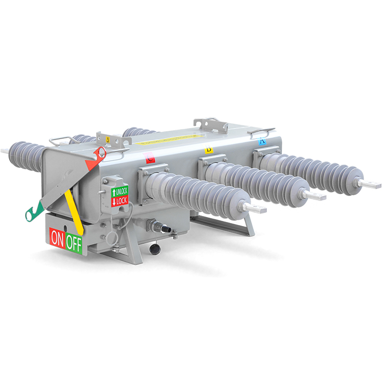
GPWF1-40.5kV is an outdoor SF6 load break switch for distribution networks with a maximum system voltage of 40.5 kV, rated current of 630 A and frequency of 50 or 60 Hz. It makes and breaks load and overload current. With an intelligent controller, it can be used for automatic sectionalizing and fault isolation. The switch body has integral silicone rubber bushings, a manual operating handle, a gas pressure gauge and mechanical position indication.
The GPWF1-40.5/630 makes and breaks load and overload current in distribution networks. Its 630 A load breaking rating is separate from its 20 kA / 4 s short-time withstand rating.
When equipped with an intelligent controller, the switch can provide automatic sectionalizing and fault isolation in automated distribution systems. Specify the controller arrangement and feeder protection coordination with the order.
The sealed tank uses SF6 as the insulation and arc-quenching medium for load and overload switching on outdoor feeders.
The structural drawing specifies integral silicone rubber bushings with a creepage distance of 1400 mm and phase spacing of 400 mm.
The switch has a manual operating handle, a manual interlock and a 24 V DC motor drive. Mechanical position indication and a pressure gauge are provided on the switch body.
| Parameter | Data |
|---|---|
| Rated Voltage | 40.5 kV |
| Rated Current | 630 A |
| Rated Frequency | 50 / 60 Hz |
| Rated Load Breaking Current | 630 A |
| Rated Short-Time Withstand Current | 20 kA / 4 s |
| Peak Withstand Current | 50 kA |
| Rated Making Current (Peak) | 50 kA |
| Rated Making Operations | 3 operations |
| Rated Load Breaking Operations | At least 400 operations |
| Mechanical Endurance | 6,000 operations |
| Operating And Auxiliary Circuit Voltage | 24 V DC |
| Main Circuit Resistance Per Phase | Not exceeding 150 µΩ |
The 630 A load breaking rating, 20 kA / 4 s short-time withstand rating and 50 kA peak making rating describe different duties. Select the switch and controller with the feeder protection scheme.
| Parameter | Data |
|---|---|
| 1-Minute Power-Frequency Withstand - Phase-To-Phase / Earth | 95 kV |
| 1-Minute Power-Frequency Withstand - Across Open Contacts | 110 kV |
| Lightning Impulse Withstand - Phase-To-Phase / Earth | 185 kV |
| Lightning Impulse Withstand - Across Open Contacts | 215 kV |
| Rain Withstand Voltage Test | 70 kV |
These are the catalog insulation values for GPWF1-40.5kV. Confirm the gas filling pressure and test conditions for the supplied configuration.
| Parameter | Data |
|---|---|
| Closed-Loop Breaking Current | 630 A |
| Active Load Breaking Current | 630 A |
| Cable Charging Breaking Current | 25 A |
| Line Charging Breaking Current | 16 A |
| No-Load Transformer Breaking Current | 21 A |
The annual relative SF6 leakage rate is specified at no more than 0.5%. Moisture limits are 150 ppm at factory delivery and 300 ppm in service.
The manual lists a low-pressure lockout and alarm range of 0.02-0.04 MPa and a high-pressure relief device operating range of 0.4-0.6 MPa. Confirm the gas filling pressure and device settings for the supplied assembly.
Check the pressure gauge against the specified gas conditions and temperature-pressure curve before operation. Use the installation and operation manual for pressure checks and servicing.
The structural drawing shows 400 mm phase spacing and 1400 mm bushing creepage distance. Confirm support dimensions, pole fittings and terminal clearances using the final assembly and installation drawings.
The secondary schematic includes motor, switch-position, low-gas-pressure and manual-locking connections. Match the control-cable pin assignments and sensing interfaces to the controller supplied.
The catalog includes outline dimensions, a secondary schematic and pole-mounting diagrams. Confirm the control-cable pin assignments and mounting hardware for the supplied assembly.
Not exceeding 3000 m above sea level.
-40°C to +50°C, with a maximum daily temperature variation of 25°C.
Daily average not exceeding 95%; monthly average not exceeding 90%.
Wind speed up to 34 m/s; seismic intensity not exceeding degree 8.
Ice thickness below 10 mm; snow thickness below 35 mm; solar irradiance below 0.1 W/cm².
Pollution Class III or IV. The site must be free from fire and explosion hazards, serious chemical corrosion and frequent severe vibration.
Send the network frequency, site conditions and pole-mounting details. Include the 24 V DC control power source, controller requirements and the sensing and control-cable interfaces needed for the feeder.