Sealed Primary System
The high voltage primary components are enclosed in a laser-welded stainless steel gas tank filled with SF6. The sealed design isolates live parts from the surrounding operating environment.


Scan To Chat On WhatsApp
GreenPower
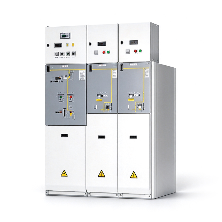
GPR1-40.5kV is a compact, modular SF6 gas insulated ring main unit, also described as box type gas insulated metal enclosed switchgear. It supports ring network and dual radial power supply for 40.5kV cable distribution systems. Load switch, switch-fuse and vacuum circuit breaker units can operate independently or be combined into a complete distribution scheme, including compact arrangements for box type substations and wind power collection networks.
The high voltage primary components are enclosed in a laser-welded stainless steel gas tank filled with SF6. The sealed design isolates live parts from the surrounding operating environment.
Choose individual functional units or a compact common-tank combination. Plug-in busbar connectors support left, right or double-sided extension according to the selected cabinet configuration.
Standard C, F and 630A V units are 430 mm wide, 1000 mm deep and 1700 mm high, helping fit secondary distribution equipment into limited installation space.
The sealed gas tank uses 3 mm stainless steel plate and laser welding. Automatic helium leak detection supports gas tightness and long service life.
The V unit combines a vacuum circuit breaker with a 3-position switch. Its rated short-circuit breaking current is 25 kA and circuit breaker mechanical life is 10,000 operations.
Cabinets connect through insulated plug-in busbar connectors. Cabinet assembly and extension do not require on-site handling of SF6 gas.
The gas tank and fuse compartment have IP67 protection. The low voltage control compartment has IP3X protection.
Interlocks coordinate switching, isolation, earthing and access to the cable compartment to help prevent dangerous misoperation.
Each gas tank has a pressure relief device that directs pressure flow toward the top or rear of the cabinet in the event of an internal fault.
Motorized operation, gas density monitoring, current transformers, fault indicators and active or self-powered protection relays can be selected for the required scheme.
| Rated Voltage | 40.5 kV |
|---|---|
| Rated Frequency | 50 Hz |
| 1 min Power Frequency Withstand Voltage | 95 kV (phase to phase / phase to earth); 118 kV (across the isolating distance) |
| Lightning Impulse Withstand Voltage | 200 kV (phase to phase / phase to earth); 220 kV (across the isolating distance) |
| Insulation Medium | SF6 gas |
| Rated SF6 Gas Pressure At 20°C | 0.02 MPa, gauge pressure |
| Annual SF6 Gas Leakage Rate | ≤ 0.1% |
| Protection Degree | Gas tank: IP67; fuse compartment: IP67; low voltage compartment: IP3X |
C, F and V units perform different switching and protection duties. Select the unit and its ratings to match the primary circuit scheme.
| Parameter | C Unit Load Switch | F Unit Switch-Fuse | V Unit Vacuum Circuit Breaker |
|---|---|---|---|
| Rated Current | 630 A | Depends on fitted fuse; main busbar 630 A | 630 / 1250 A |
| Short-Circuit Breaking Current | — | 31.5 kA, subject to fuse selection | 25 kA |
| Short-Time Withstand Current / Duration | 20 kA / 3 s | — | 25 kA / 4 s |
| Peak Withstand Current | 50 kA | — | 63 kA |
| Short-Circuit Making Current (Peak) | 50 kA | Depends on fitted fuse | 63 kA |
| Active Load Breaking Current | 630 A | 630 A | — |
| Closed-Loop Breaking Current | 630 A | — | — |
| Cable Charging Breaking Current | 50 A | — | 50 A |
| Mechanical Life | Load switch: 5000 operations Earthing switch: 2000 operations | Load switch: 3000 operations Earthing switch: 2000 operations | VCB: 10,000 operations 3-position switch: 2000 operations |
| VCB Rated Operating Sequence | — | — | O-0.3s-CO-180s-CO |
F-unit rated current and making capability depend on the selected fuse. The selection manual lists 31.5 kA short-circuit breaking capability for the switch-fuse combination; confirm the complete fuse and transformer protection selection for the project. A dash indicates that no rating is listed for that function in the main parameter table.
A 630A unit for incoming and outgoing feeder switching. It includes a spring-operated load switch, an earthing switch and mechanical interlocking, with motorized load switch operation available as an option.
Combines a load switch and high breaking capacity fuse for transformer control and protection up to 2000 kVA. Dual earthing arrangements allow both sides of the fuse to be earthed for replacement.
Available in 630A and 1250A versions for feeder, motor and transformer protection. Active or self-powered relays provide selectable overcurrent, short-circuit and earth-fault protection functions.
IL/IR busbar switch units, RB busbar riser units and RCL/RCR cable incoming units support sectionalizing and cable connection schemes. Compact common-tank arrangements include CC, CV, CCV, CCC and CCF.
-25°C to +40°C, with a maximum daily average temperature of +35°C.
Up to 1000 m under normal service conditions. Higher altitude applications require technical confirmation.
Daily average ≤ 95%; monthly average ≤ 90%. Daily and monthly average water vapor pressure limits are 2.2 kPa and 1.8 kPa respectively.
Normal service conditions exclude significant dust, smoke, corrosive or combustible gases, vapor and salt mist. Special climatic or pollution conditions should be agreed during project review.
Individual functional units and compact combinations share a standard depth of 1000 mm and height of 1700 mm in the configurations below. An optional top-mounted low voltage control compartment adds 200 mm or 500 mm in height.
| Configuration | Width (mm) | Depth (mm) | Height (mm) |
|---|---|---|---|
| C / F / V-630A | 430 | 1000 | 1700 |
| V-1250A | 600 | 1000 | 1700 |
| IL / IR Busbar Switch | 600 | 1000 | 1700 |
| RB / RCL / RCR | 430 | 1000 | 1700 |
| CC Compact Combination | 860 | 1000 | 1700 |
| CV Compact Combination | 1030 | 1000 | 1700 |
| CCV Compact Combination | 1460 | 1000 | 1700 |
The table lists basic cabinet dimensions and the compact combinations specified in the selection manual. Outline views may show different configured heights. Confirm the final arrangement, control compartment, cable terminations and foundation drawing before installation.
The series can be arranged in an outdoor switch station or box type substation. Select the enclosure, cable access, site ventilation and environmental provisions for the installation conditions.
Motorized mechanisms and a low voltage control compartment support local or remote switching. Gas density relays, protection relays, current transformers and fault indicators are available according to the required control scheme.
The selection manual lists the following design references. Required standard editions and project-specific compliance are confirmed during technical review.
| Common Specifications | IEC 62271-1; GB/T 11022-2011; DL/T 593-2006 |
|---|---|
| AC Metal Enclosed Switchgear | IEC 62271-200; GB 3906-2006; DL/T 404-2007 |
| Load Switches | IEC 62271-103; GB 3804-2004 |
| Switch-Fuse Combinations | IEC 62271-105; GB 16926-2009 |
| Disconnectors And Earthing Switches | IEC 62271-102; GB 1985-2004 |
| AC Circuit Breakers | IEC 62271-100; GB 1984-2014 |
| Cable Accessories | IEC 60502-4; GB/T 12706.4-2008 |
40.5kV cable networks for collecting and transmitting power from wind generation equipment.
Compact switching and transformer protection schemes for secondary substations and outdoor distribution stations.
Ring network or dual radial supply for industrial areas, commercial buildings and rural towns with concentrated electrical loads.
Cable distribution applications in airports, rail transit, mines and remote substations, with the configuration selected for site conditions.
Share the required current, primary circuit scheme, transformer capacity and site conditions for configuration and quotation review.