Earth-Fault Current Limitation
The resistor forms the neutral-to-earth connection. Its resistance, short-time current and duration are selected together to match the required earth-fault duty.


Scan To Chat On WhatsApp
GreenPower
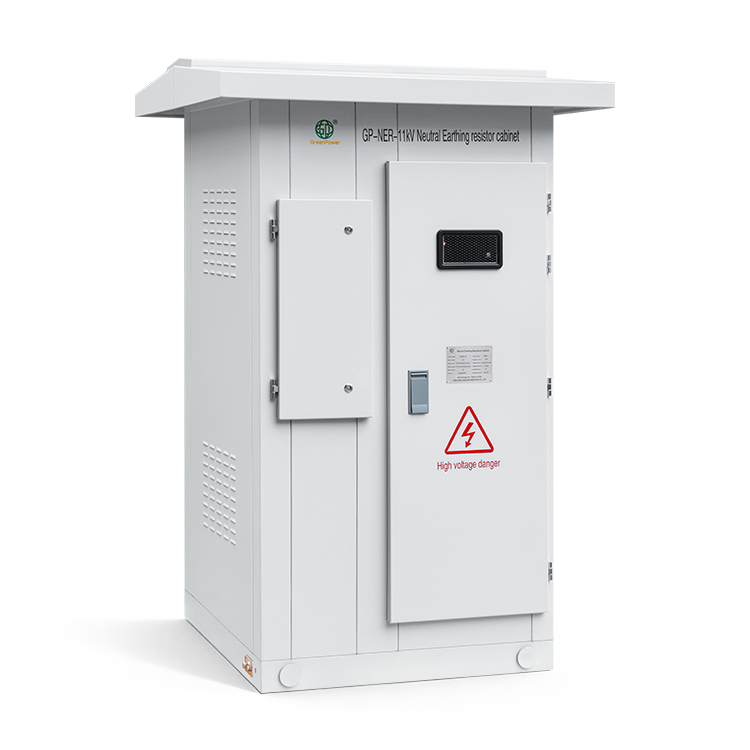
GP-NER-11kV connects the neutral of an 11 kV system to earth through a resistor to limit earth-fault current. The catalog configuration combines a 250 Ω ±5% stainless-steel resistor rated 25 A for 10 s, a manually operated GN19-12/400 disconnector and a protection current transformer in an IP54 outdoor cabinet. Each assembly is specified to suit the system earthing and protection requirements.
The resistor forms the neutral-to-earth connection. Its resistance, short-time current and duration are selected together to match the required earth-fault duty.
The GN19-12/400 disconnector is manually operated. Its auxiliary contacts are brought to the XT2 terminal block for the external status circuit.
The cabinet includes a GN19-12/400 disconnector for isolation during maintenance, with the operating arrangement shown in the outline drawing.
An LZZBJ9-10 current transformer provides a 100/5 A signal for the external protection circuit. The specified CT class is 5P10, with a 5 VA burden.
The cabinet uses 2 mm cold-rolled steel plate, finished in RAL7035, with a rain canopy, front and rear doors, and ventilation openings lined with dust-proof mesh.
| Parameter | Data |
|---|---|
| System Rated Voltage | 11 kV |
| Short-Time Current | 25 A |
| Duration Of Short-Time Current | 10 s |
| Nominal Resistance | 250 Ω |
| Resistance Tolerance | ±5% |
| Resistor Material | Stainless steel |
| Disconnector | GN19-12/400, manual operation |
| Current Transformer Model | LZZBJ9-10 |
| Current Transformer Ratio | 100/5 A |
| CT Protection Class | 5P10 |
| CT Rated Burden | 5 VA |
| Installation | Outdoor |
| Enclosure Protection | IP54 |
| Cabinet Dimensions (W × D × H) | 1000 × 1150 × 2000 mm |
| Cabinet Material | 2 mm cold-rolled steel plate |
| Cabinet Colour | RAL7035 |
| Base | No. 10 channel steel |
These values describe the 11 kV, 25 A / 10 s configuration in the catalog drawings. Resistance, current, duration and enclosure requirements are confirmed for each order.
The cabinet measures 1000 × 1150 × 2000 mm (W × D × H). Primary, earthing and secondary cables enter from below through openings fitted with rubber rings and cable clamps. The channel-steel base has copper earthing blocks on both sides with M12 threaded holes.
The primary schematic places the disconnector, resistor and CT in the neutral-to-earth circuit. CT secondary connections are shown at XT1, and disconnector auxiliary contacts at XT2, for connection to the external protection and status circuits.
The manual includes cabinet views, internal arrangements, the base plan and wiring diagrams. Use the supplied assembly drawings to confirm the foundation, cable openings and terminal connections.
Not exceeding 4000 m above sea level.
-40°C to +60°C.
Not exceeding 95% at 25°C.
48-52 Hz for 50 Hz systems; 58-62 Hz for 60 Hz systems.
The installation site should be free from corrosive gases, steam and explosive dust. State any special operating conditions with the enquiry.
Provide the system voltage, neutral arrangement, required earth-fault current, resistance and short-time duration. Include the CT ratio, protection class, burden and terminal requirements. Systems without an accessible neutral may require an earthing transformer as part of the earthing scheme.
Specify any earth-fault event recording, temperature and humidity control, or monitoring interface required. Confirm the enclosure material, protection level, installation location and cable entry arrangement with the order.
Send the system voltage, required earth-fault current, resistance and duration. Include the neutral arrangement, CT requirements and installation details for your project.