Rotary Contact Construction
The contacts rotate within an upper-and-lower arrangement on a shared frame. This layout keeps the switch compact for installation in indoor switchgear.


Scan To Chat On WhatsApp
GreenPower
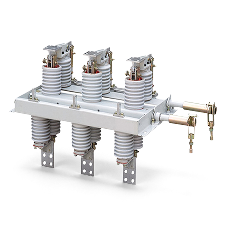
GN30-12kV is an indoor rotary disconnector for 12 kV, 50 Hz systems, with rated-current versions from 630 A to 3150 A. Two groups of insulators and contacts are mounted above and below a common three-phase frame, and rotating contacts open or close the circuit. GN30-12D models add an earthing blade.
The contacts rotate within an upper-and-lower arrangement on a shared frame. This layout keeps the switch compact for installation in indoor switchgear.
The disconnector provides circuit isolation when no load current is flowing. Select it for isolation duty and coordinate operation with the circuit breaker or other load-switching device.
The series includes 630, 1000, 1250, 2000, 2500 and 3150 A versions. Match the current rating and corresponding short-time and peak withstand ratings to the circuit.
GN30-12D adds an earthing blade to the standard GN30-12 switch. Specify the earthing arrangement with the required current version and switchgear layout.
The rotary disconnector can be installed with indoor switchgear or used separately. Match the support, operating linkage and terminal positions to the installation.
Rated frequency: 50 Hz. The ratings below apply to the standard and D-type earthing versions of the 12 kV series.
| Model | Rated Current | Short-Time Withstand (r.m.s.) | Peak Withstand |
|---|---|---|---|
| GN30-12(D)/630A | 630 A | 20 kA / 4 s | 50 kA |
| GN30-12(D)/1000A | 1000 A | 31.5 kA / 4 s | 80 kA |
| GN30-12(D)/1250A | 1250 A | 31.5 kA / 4 s | 80 kA |
| GN30-12(D)/2000A | 2000 A | 40 kA / 4 s | 100 kA |
| GN30-12(D)/2500A | 2500 A | 40 kA / 4 s | 100 kA |
| GN30-12(D)/3150A | 3150 A | 40 kA / 4 s | 100 kA |
The standard GN30-12 version uses rotary contacts to make or break the isolation gap. Choose the rated-current version to suit the circuit and installation space.
GN30-12D includes an additional earthing blade. Confirm the blade arrangement, operating sequence and required interlocks with the selected assembly.
Use the GN30-12(D) outline and installation drawing matching the rated current and earthing version. Check the mounting surface, terminal positions and available installation space before selection.
Specify the operating mechanism and linkage arrangement with the switch. Check the mounting surface, terminal connections and full contact travel against the switchgear layout.
-10°C to +40°C for the general indoor configuration.
Not exceeding 1000 m above sea level.
Daily average not exceeding 95%; monthly average not exceeding 90%.
Daily average up to 2.2 kPa; monthly average up to 1.8 kPa.
The manual lists a -25°C lower limit for cold-region arrangements. Confirm this requirement separately from the general indoor configuration.
Indoor locations without fire or explosion hazards, serious pollution, chemical corrosion or severe vibration.
Send the rated current and required fault withstand ratings. Include the earthing requirement, switchgear layout, operating linkage and available installation space so the correct model and drawing can be selected.