No-Load Circuit Isolation
Designed to open and close a circuit when voltage is present but no load current is flowing. Operation must follow the no-load switching duty specified for the disconnector.


Scan To Chat On WhatsApp
GreenPower
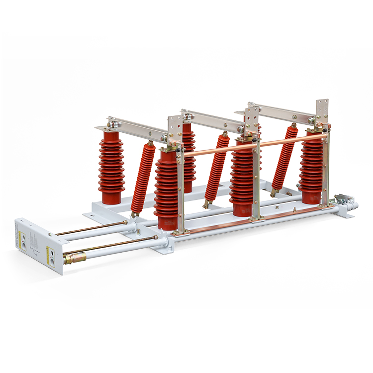
GN27-40.5kV is a three-phase indoor high-voltage disconnector for 40.5 kV, 50/60 Hz AC systems. It opens and closes circuits under no-load conditions and uses a common-base knife-blade structure. The series covers rated currents from 630 A to 2000 A, with manual operation using the CS6-1 mechanism and several outline arrangements for installation planning.
Designed to open and close a circuit when voltage is present but no load current is flowing. Operation must follow the no-load switching duty specified for the disconnector.
The three phases share a common base and operating shaft. Operating insulators transmit shaft movement to the blades for opening and closing.
Each phase uses two spring-loaded blades on the contact base, forming the moving part of the current path.
The fixed contacts use spring-loaded contact fingers with vertical compliance to support reliable blade engagement.
The series includes standard, C1, D1, C1D2, ST and MJ outline arrangements. Match the selected model to the installation drawing.
Short-time and peak withstand ratings depend on the rated-current version. Use the matching column when selecting a model.
| Parameter | 630 A | 1250 A | 1600 A | 2000 A |
|---|---|---|---|---|
| Rated Voltage | 40.5 kV | 40.5 kV | 40.5 kV | 40.5 kV |
| Rated Frequency | 50 / 60 Hz | 50 / 60 Hz | 50 / 60 Hz | 50 / 60 Hz |
| Rated Current | 630 A | 1250 A | 1600 A | 2000 A |
| Short-Time Withstand Current (r.m.s.), 4 s | 20 kA | 31.5 kA | 31.5 kA | 40 kA |
| Peak Withstand Current | 50 kA | 80 kA | 80 kA | 100 kA |
| Rated Lightning Impulse Withstand Voltage | 200 kV | 200 kV | 200 kV | 200 kV |
During opening, the operating crank turns the main shaft and the operating insulators lift the blades away from the fixed contacts. Turning the shaft in the opposite direction pulls the blades downward into the fully closed position.
The frame uses bent plates and angle steel with six support insulators, two per phase. The fixed contacts and spring-loaded blades form the conducting path, while the operating insulators provide the mechanical drive.
The catalog provides six outline and mounting drawings with 460 mm phase spacing. Select the exact configuration and check its mounting points and operating clearance before installation.
| Model Shown In Catalog | Rated Current Shown | Phase Spacing |
|---|---|---|
| GN27-40.5/630A-460 | 630 A | 460 mm |
| GN27-40.5C1/630A-460 | 630 A | 460 mm |
| GN27-40.5D1/630A-460 | 630 A | 460 mm |
| GN27-40.5C1D2/1600A-460 | 1600 A | 460 mm |
| GN27-40.5ST/630A-460 | 630 A | 460 mm |
| GN27-40.5MJ/630A-460 | 630 A | 460 mm |
Download the catalog for the complete dimensioned drawings. The MJ outline includes an electric motor; confirm the required operating mechanism and control supply when ordering this arrangement.
1000 to 3000 m.
-25°C to +40°C, with a daily average not exceeding +35°C.
Daily average not exceeding 95%; monthly average not exceeding 90%.
Not exceeding degree 8.
Indoor locations free from fire or explosion hazards, severe pollution, chemical corrosion and severe vibration.
Conditions outside these limits require agreement between the user and the manufacturer.
Please specify the model and configuration, rated voltage, rated current, required withstand ratings, operating mechanism and site conditions. Include the applicable outline drawing and any special installation requirements.