No-Load Circuit Isolation
The switch connects, disconnects or transfers a circuit when voltage may be present but no load current is flowing. Its fault withstand ratings describe current carrying duty, rather than load or fault interruption.


Scan To Chat On WhatsApp
GreenPower
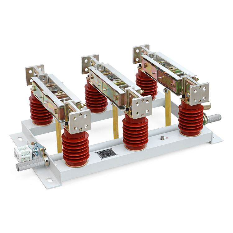
GN22-12(C)(D) is a series of 12 kV, 50 Hz indoor disconnectors for high-current circuits. Rated-current versions range from 2000 A to 8000 A. The three-phase knife switch uses a common base and a two-step closing and contact-locking action. Flat-mounted, through-wall and earthing configurations are available, with manual or motorized operating mechanisms.
The switch connects, disconnects or transfers a circuit when voltage may be present but no load current is flowing. Its fault withstand ratings describe current carrying duty, rather than load or fault interruption.
The three phases share a frame and operating shaft. Six support insulators, two per pole, support the conducting parts; operating insulators transmit shaft movement to the blades.
The blade first moves into the closed position, then the mechanism locks the contact assembly. This separates blade movement from final contact compression.
Earthing versions are available on the moving-contact side, fixed-contact side, or both sides. Select the earthing arrangement with the switch structure.
CS6-1 and CS6-2 manual mechanisms are listed in the manual, together with electric operating mechanisms. The operating mechanism can be arranged on the left or right.
All versions below are rated 12 kV, 50 Hz. Short-time and peak withstand currents depend on the rated-current version.
| Model | Rated Current | Short-Time Withstand (r.m.s.) | Peak Withstand |
|---|---|---|---|
| GN22-12(C)(D)/2000A | 2000 A | 50 kA / 4 s | 100 kA |
| GN22-12(C)(D)/2500A | 2500 A | 50 kA / 4 s | 125 kA |
| GN22-12(C)(D)/3150A | 3150 A | 50 kA / 4 s | 125 kA |
| GN22-12(C)(D)/4000A | 4000 A | 50 kA / 4 s | 125 kA |
| GN22-12(C)(D)/5000A | 5000 A | 100 kA / 4 s | 250 kA |
| GN22-12(C)(D)/6300A | 6300 A | 100 kA / 4 s | 250 kA |
| GN22-12(C)(D)/8000A | 8000 A | 100 kA / 4 s | 250 kA |
The 2000 A version has a 100 kA peak withstand rating; the 2500-4000 A versions are rated 125 kA peak. The 5000-8000 A versions are rated 100 kA for 4 s and 250 kA peak.
Choose a manual or motorized mechanism and specify the left- or right-hand mounting arrangement. The manual includes a split motorized installation example for GN22-12ST/3150-250.
After the blade reaches its closed travel limit, the shaft continues rotating by approximately 10° to lock the contact assembly. The switch must reach its locked position before it is put into service.
The series includes flat-mounted and through-wall arrangements, each with earthing versions. Match the selected structure to the switchgear layout and the required terminal positions.
Specify earthing on the moving-contact side, fixed-contact side or both sides. Check blade travel, operating linkage, mounting points and clearances against the selected assembly drawing.
The catalog contains outline drawings for standard, C, D, CD and ST configurations, including a split motorized installation. Dimensions and phase spacing depend on the selected arrangement; request the final drawing for the ordered model.
-15°C to +40°C, with a daily average not exceeding +35°C.
Not exceeding 1000 m above sea level.
Daily average not exceeding 95%; monthly average not exceeding 90%.
Daily average not exceeding 2.2 kPa; monthly average not exceeding 1.8 kPa.
Not exceeding degree 8.
Indoor locations without fire or explosion hazards, severe pollution, chemical corrosion or severe vibration. Conditions outside these limits require prior review.
Send the rated current and fault withstand requirements. Include the mounting type, earthing position, left- or right-hand drive arrangement and available installation space. For motorized operation, specify the control power supply.